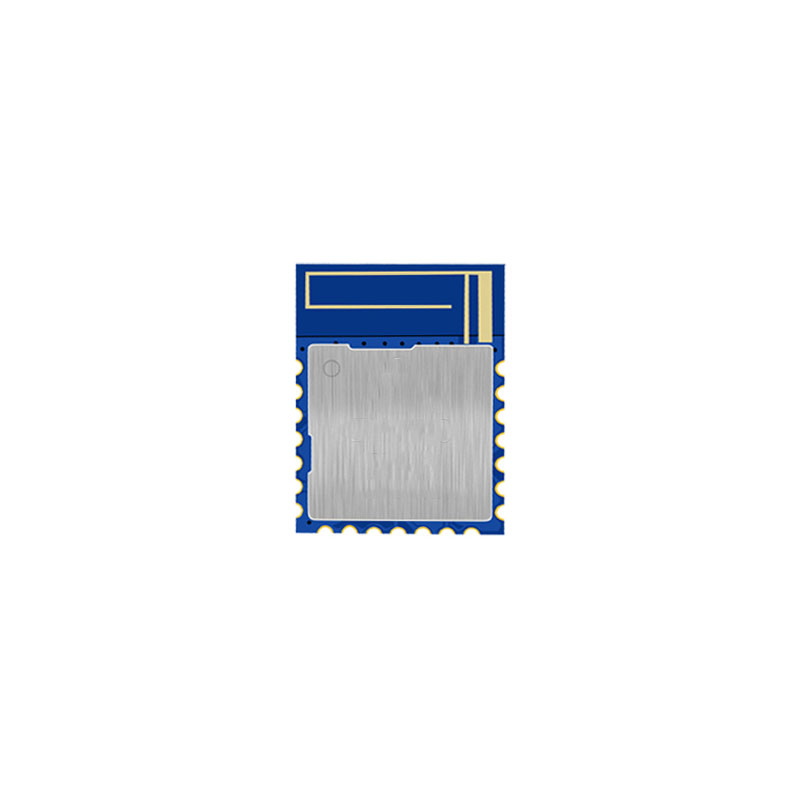
Most Bluetooth modules advertise a “line-of-sight range” of 50 to 100 meters at 0 dBm. In a warehouse with metal racking, concrete walls, and 2.4 GHz congestion, that number drops to 10-15 meters — sometimes less. When your asset tracking system needs 50 meters of reliable indoor coverage, you have two options: deploy five times more gateways, or extend the RF range of the module itself. This article covers the second approach: integrating Power Amplifiers (PA) and Low-Noise Amplifiers (LNA) into a BLE module, calculating the real link budget, and navigating the trade-offs with power consumption, coexistence, and regulatory limits.
1. Why Raw TX Power Is Not Enough
Range is determined by two things: how loud you can shout (TX power) and how quietly you can listen (receiver sensitivity). A common mistake is to focus only on the TX side — adding a +20 dBm PA — while ignoring the receive path. BLE is bidirectional: the module must not only transmit advertisements but also receive scan requests, connection packets, and data.
If the gateway can hear the tag at 100 meters but the tag cannot hear the gateway’s response, the link fails. This is the link asymmetry problem: extending only TX range creates a one-way link that appears to work in RSSI logs but fails at the protocol level.
A balanced range extension requires improving both:
– TX path: PA boosts output power from 0 dBm to +20 dBm (100x power)
– RX path: LNA improves sensitivity by 10-15 dB
– Antenna path: Higher gain antenna or diversity
2. Link Budget Fundamentals
2.1 The Two-Way Link Budget
For a BLE link to work, both directions must close:
TX_power_module + G_TX_antenna - Path_Loss - G_RX_antenna >= RX_sensitivity_gateway
TX_power_gateway + G_TX_antenna - Path_Loss - G_RX_antenna >= RX_sensitivity_module
The limiting direction is whichever has the smaller margin. In most BLE systems, the gateway has higher TX power and better sensitivity (mains-powered, larger antenna), while the module is battery-constrained. So the module-to-gateway direction is usually the bottleneck — but only if the module has a PA.
If the module has a PA but no LNA, the gateway-to-module direction becomes the bottleneck. The module can shout but cannot hear.
2.2 Path Loss Models
Free-space path loss (FSPL) at 2.4 GHz:
FSPL(dB) = 20 * log10(d) + 40.05 (d in meters)| Distance | FSPL | TX Power Needed for -90 dBm RX |
|---|---|---|
| 10 m | 60.1 dB | -29.9 dBm |
| 50 m | 74.0 dB | -16.0 dBm |
| 100 m | 80.1 dB | -9.9 dBm |
| 300 m | 89.6 dB | -0.4 dBm |
| 500 m | 94.1 dB | +4.1 dBm |
| 1000 m | 100.1 dB | +10.1 dBm |
Indoor path loss is worse. A practical indoor model:
PL_indoor(dB) = FSPL + N_walls * Wall_Loss + Floor_Loss + Shadowing_MarginTypical values:
– Drywall: 3-5 dB per wall
– Concrete wall: 10-15 dB per wall
– Metal door: 20-30 dB
– Floor (concrete): 15-20 dB per floor
– Shadowing margin (95% coverage): 8-12 dB
Example: 100 meters through 3 drywall walls and 1 concrete wall:
PL = 80.1 + 3*4 + 12 + 10 = 114.1 dBAt this loss, a 0 dBm module with -90 dBm sensitivity has a margin of -24.1 dB — the link fails. A +20 dBm PA module with -105 dBm sensitivity (LNA) has a margin of +10.9 dB — the link closes.
2.3 Fade Margin and Reliability
Link margin is not just about “does it work.” It determines reliability:
| Link Margin | Packet Error Rate (approx) | Practical Meaning |
|---|---|---|
| 0 dB | ~50% | Intermittent, unusable |
| 5 dB | ~20% | Marginal, frequent retransmissions |
| 10 dB | ~5% | Usable with retransmissions |
| 15 dB | ~1% | Reliable for most applications |
| 20 dB | <0.1% | Robust, handles multipath and interference |
| 30 dB | <0.01% | Industrial grade, immune to most fading |
Target 15-20 dB margin for production deployments. This means your link budget should have 15-20 dB of headroom beyond the minimum required to close the link.
3. PA Integration
3.1 PA Selection Criteria
Key parameters for BLE PA selection:
| Parameter | Typical BLE | With External PA | Impact |
|---|---|---|---|
| Output power | 0 to +4 dBm | +10 to +20 dBm | Range |
| Gain | N/A | 15-25 dB | Drives module output |
| Current (TX) | 5-8 mA | 30-120 mA | Battery life |
| Noise figure (RX bypass) | N/A | 1.5-3 dB | RX sensitivity |
| Harmonic suppression | -40 dBc | -50 dBc required | Regulatory |
| Turn-on time | N/A | 1-5 us | Timing budget |
BLE modulation is GFSK with ±250 kHz deviation (1 Mbps) or ±500 kHz (2 Mbps). The PA must handle this without amplitude-to-phase conversion (AM-PM distortion), which corrupts the FSK signal. Linear PAs are preferred over saturated PAs for BLE.
3.2 PA Topologies
Discrete PA (Class A/AB):
– Gain: 15-20 dB
– Linearity: Good (suitable for GFSK)
– Efficiency: 25-35% (Class AB)
– Current at +20 dBm: ~80-120 mA
– Best for: Maximum linearity, moderate power
Integrated Front-End Module (FEM):
– Combines PA + LNA + T/R switch in one package
– Gain: 20-25 dB (PA), 12-15 dB (LNA)
– Current at +20 dBm: 60-100 mA
– Footprint: 2×2 mm to 3×5 mm
– Best for: Compact designs, fast time-to-market
Examples of common BLE FEMs:
| Part | PA Gain | PA Pout | LNA Gain | NF | TX Current | Supply |
|---|---|---|---|---|---|---|
| Skyworks SKY66112 | 20 dB | +20 dBm | 13 dB | 1.7 dB | 85 mA | 3.3V |
| Nordic nRF21540 | 20 dB | +20 dBm | 13 dB | 1.5 dB | 78 mA | 3.3V |
| Qorvo QPL9547 | 22 dB | +22 dBm | 14 dB | 1.4 dB | 95 mA | 3.3V |
| Broadcom BCM477 | 18 dB | +18 dBm | 12 dB | 2.0 dB | 65 mA | 3.3V |
3.3 Output Matching Network
The PA output must be matched to 50 ohms antenna impedance. A typical matching network for 2.4 GHz:
PA_out -- [Series L] -- [Shunt C] -- [Series L] -- AntennaComponent values depend on the PA’s optimal load impedance (Z_opt). For a FEM, the datasheet usually specifies Z_opt at the output pin (e.g., 32 + j12 ohms). The matching network transforms this to 50 ohms.
Key design rules:
– Use high-Q inductors (Q > 30 at 2.4 GHz) to minimize insertion loss
– Keep matching network traces short (< 2 mm) to reduce parasitic effects
– Include a DC blocking capacitor (100 pF) at the PA output
– Verify with a VNA: S11 < -10 dB across 2.4-2.483 GHz
3.4 Harmonic Filtering
A PA generating +20 dBm fundamental will typically produce second harmonics at -15 to -25 dBc — that is +5 to -5 dBm at 4.8 GHz. FCC Part 15 requires spurious emissions below -41.25 dBm/MHz EIRP in restricted bands (which includes 4.8 GHz). A low-pass or bandpass filter is mandatory:
PA_out -- Matching Network -- LPF (2.4 GHz) -- AntennaA 3rd-order elliptic low-pass filter provides > 40 dB attenuation at 4.8 GHz with < 0.5 dB insertion loss at 2.4 GHz:
| Stage | Component | Value |
|---|---|---|
| Series | Inductor | 2.2 nH |
| Shunt | Capacitor | 1.2 pF |
| Series | Inductor | 2.2 nH |
| Shunt | Capacitor (to ground) | 1.0 pF |
| Shunt | Inductor (to ground, harmonic trap at 4.8 GHz) | 1.1 nH |
The harmonic trap (shunt inductor to ground, series capacitor) resonates at 4.8 GHz, creating a short circuit at the harmonic frequency while passing 2.4 GHz.
4. LNA Integration
4.1 Why LNA Matters
Receiver sensitivity is determined by the system noise figure:
NF_total = NF_1 + (NF_2 - 1) / G_1 + (NF_3 - 1) / (G_1 * G_2) + ...The first stage dominates. A typical BLE SoC has NF = 6-8 dB. Adding an LNA with NF = 1.5 dB and gain = 13 dB as the first stage:
NF_total = 1.5 + (7 - 1) / 20 = 1.5 + 0.3 = 1.8 dBSensitivity improvement = 7 dB – 1.8 dB = 5.2 dB. That corresponds to approximately 1.8x range improvement (at 5.2 dB / 6 dB per doubling = ~1.8x).
With a better BLE SoC (NF = 5 dB), the improvement is larger:
NF_total = 1.5 + (5 - 1) / 20 = 1.5 + 0.2 = 1.7 dB
Sensitivity improvement = 5 - 1.7 = 3.3 dB
4.2 LNA Bias and Power
An LNA draws current even when not needed — during TX and during idle. A FEM with bypass mode routes the signal around the LNA during TX, but the LNA bias circuitry must be disabled:
| Mode | LNA Current | PA Current | Total FEM Current |
|---|---|---|---|
| RX (LNA active) | 3-5 mA | 0 | 3-5 mA |
| TX (PA active) | 0 (disabled) | 60-100 mA | 60-100 mA |
| Bypass (idle) | < 1 uA | < 1 uA | < 1 uA |
The module firmware must control the FEM’s mode pins (TXEN, RXEN) in sync with the BLE radio state machine. Timing is critical — the FEM must switch from TX to RX mode within the BLE inter-frame spacing (150 us for BLE 5).
4.3 Noise Figure Degradation from Matching
A poorly designed input matching network can add 1-3 dB of insertion loss before the LNA, directly degrading the noise figure. Best practices:
– Place LNA input as close to the antenna as possible (< 5 mm)
– Minimize switch loss (each FEM T/R switch adds 0.5-1 dB)
– Use a matching network with < 0.3 dB insertion loss
– Total RX chain loss before LNA should be < 0.5 dB
A 0.5 dB insertion loss before the LNA directly reduces sensitivity by 0.5 dB — equivalent to losing 6% of range.
5. T/R Switch Design
5.1 The Antenna Sharing Problem
BLE uses one antenna for both TX and RX. When a PA and LNA are added, the antenna must be shared between the high-power TX path and the sensitive RX path. Three approaches:
5.2 Integrated T/R Switch (FEM)
Most FEMs include a built-in T/R switch controlled by TXEN/RXEN pins. Insertion loss: 0.5-1.0 dB. Isolation: 20-30 dB. This is the simplest approach and recommended for most designs.
5.3 External SPDT Switch
For designs using discrete PA and LNA, an external SPDT RF switch is needed:
| Switch Type | Insertion Loss | Isolation | Switching Time | Cost |
|---|---|---|---|---|
| PIN diode | 0.3 dB | 30 dB | 100 ns | Low |
| CMOS SPDT | 0.5 dB | 25 dB | 300 ns | Medium |
| GaAs pHEMT | 0.4 dB | 35 dB | 50 ns | High |
The switch must handle the PA’s peak output power (+20 dBm = 100 mW) without compression. Most CMOS switches handle +25 dBm; PIN diode switches can handle +30 dBm.
5.4 Timing Diagram
BLE connection event timing with FEM:
FEM Mode
Module TX ──────────────────┐    ┌── RX Window ───
│    │
TXEN ───────────────────────┘    │
│
RXEN ────────────────────────────┘
│
150 us (T_IFS)
The FEM must settle within the BLE inter-frame spacing (T_IFS = 150 us). Most FEMs settle in 1-5 us, leaving comfortable margin.
6. Power Consumption Impact
6.1 Current Budget Comparison
A BLE module advertising at 500 ms interval, 0 dBm, no FEM:
| State | Current | Duration | Charge per event |
|---|---|---|---|
| Sleep | 2 uA | 499 ms | 0.998 uC |
| Wake + setup | 8 mA | 0.3 ms | 2.4 uC |
| TX (0 dBm) | 8 mA | 0.376 ms | 3.0 uC |
| Total per adv | 6.4 uC | ||
| Average current | 12.8 uA |
Same module with FEM at +20 dBm:
| State | Current | Duration | Charge per event |
|---|---|---|---|
| Sleep | 2 uA | 498.5 ms | 0.997 uC |
| Wake + setup | 8 mA | 0.3 ms | 2.4 uC |
| FEM TX enable + settle | 2 mA | 0.1 ms | 0.2 uC |
| TX (+20 dBm) | 88 mA | 0.376 ms | 33.1 uC |
| FEM disable | 0.5 mA | 0.1 ms | 0.05 uC |
| Total per adv | 36.75 uC | ||
| Average current | 73.5 uA |
The FEM increases average current from 12.8 uA to 73.5 uA — a 5.7x increase. For a CR2032 battery (220 mAh, derated to 160 mAh at BLE loads):
– No FEM: 160 mAh / 0.0128 mA = 12,500 hours (~17 months)
– With FEM: 160 mAh / 0.0735 mA = 2,177 hours (~3 months)
This is a dramatic trade-off. The FEM’s 85 mA TX current dominates the power budget.
6.2 Mitigation Strategies
Duty-cycle the PA: Only use +20 dBm for long-range tags; use 0 dBm (bypass mode) for nearby tags. The module can adjust TX power per-connection or per-advertisement. This requires the gateway to measure RSSI and feed back a power adjustment command.
Adaptive advertising: Use +20 dBm every 10th advertisement, 0 dBm for the rest. Detection probability drops but average current drops proportionally:
| Strategy | Adv at +20 dBm | Adv at 0 dBm | Average Current | Range (effective) |
|---|---|---|---|---|
| All +20 dBm | 100% | 0% | 73.5 uA | Full range |
| 50/50 | 50% | 50% | 43.2 uA | Full range (50% of time) |
| 10% +20 dBm | 10% | 90% | 18.7 uA | Full range (10% of time) |
| All 0 dBm (bypass) | 0% | 100% | 12.8 uA | Short range |
The 10% strategy is popular: it maintains long-range detectability while keeping battery life at ~12 months.
7. Coexistence Trade-offs
7.1 BLE + WiFi Coexistence
When a module supports both BLE and WiFi (e.g., ESP32), the +20 dBm BLE PA and WiFi transmitter share the 2.4 GHz band. Key issues:
– Desensitization: WiFi TX at +20 dBm can desensitize the BLE LNA by 20-40 dB if both are active simultaneously. Coexistence hardware (PTA — Packet Traffic Arbitration) is mandatory.
– Harmonic interaction: WiFi 2.4 GHz harmonics can fall into BLE channels and vice versa.
– Antenna isolation: If BLE and WiFi share an antenna, a diplexer is needed. If separate antennas, maintain > 20 dB isolation.
7.2 PTA (Packet Traffic Arbitration)
PTA is a 3-wire or 4-wire interface between the BLE and WiFi MAC layers:
BLE_REQ  --> WiFi  (BLE requests airtime)
WiFi_GRANT --> BLE  (WiFi grants/denies)
BLE_PRI  --> WiFi  (BLE has priority, optional)
When BLE is transmitting at +20 dBm, the WiFi receiver must be muted to avoid front-end overload. The PTA coordinates this:
1. BLE asserts BLE_REQ before TX
2. WiFi checks if it can yield (no critical TX/RX in progress)
3. WiFi asserts WiFi_GRANT
4. BLE TX + FEM active
5. BLE deasserts BLE_REQ
6. WiFi resumes
Latency impact: 50-200 us per arbitration cycle. For BLE advertising (one-way, no response needed), PTA is less critical. For BLE connections, PTA adds jitter.
7.3 Adjacent Channel Rejection with LNA
An LNA with 13 dB gain amplifies not just the desired signal but also adjacent channel interference. A nearby WiFi transmitter at +20 dBm on an adjacent frequency can saturate the LNA:
| WiFi TX Power | Frequency Offset | LNA Output | LNA Status |
|---|---|---|---|
| +20 dBm | 2 MHz (adjacent) | +33 dBm | Saturated (P1dB = +10 dBm) |
| +20 dBm | 10 MHz | +33 dBm | Saturated |
| +20 dBm | 20 MHz | +33 dBm | Saturated |
| +10 dBm | 2 MHz | +23 dBm | Saturated |
| 0 dBm | 2 MHz | +13 dBm | Near compression |
| -20 dBm | 2 MHz | -7 dBm | Linear |
When the LNA is saturated, it cannot receive any BLE signal — the module is deaf. Solutions:
– Add a SAW filter before the LNA (rejects out-of-band WiFi)
– Use an LNA with higher P1dB (> +15 dBm)
– Implement WiFi/BLE time-division coexistence (PTA)
A SAW filter adds 1.5-2.5 dB insertion loss, partially negating the LNA benefit. But it prevents saturation, which is worse.
8. Regulatory Considerations
8.1 FCC (US)
– Maximum EIRP: +36 dBm (4 W) for spread spectrum/digital modulation in 2.4 GHz ISM
– Must demonstrate at least 6 dB of processing gain or be digitally modulated
– Spurious emissions: < -41.25 dBm/MHz EIRP in restricted bands
– Harmonic filtering is mandatory for +20 dBm PAs
A +20 dBm PA with a 2 dBi antenna gives +22 dBm EIRP — well within the +36 dBm limit. But the second harmonic at 4.8 GHz must be below -41.25 dBm/MHz, requiring > 63 dB harmonic suppression.
8.2 CE/ETSI (Europe)
– Maximum EIRP: +20 dBm (100 mW) for 2.4 GHz wideband data transmission
– This is significantly more restrictive than FCC
– A +20 dBm PA with any antenna gain exceeds the limit
– Maximum PA output: +20 dBm with 0 dBi antenna, or +17 dBm with 3 dBi antenna
For European deployments, the FEM’s +20 dBm capability cannot be fully utilized. Practical limit: +14 to +17 dBm PA output with standard dipole antenna.
8.3 SRRC (China)
– Maximum EIRP: +20 dBm (100 mW) — same as ETSI
– Spurious: < -36 dBm/MHz for > 1 GHz
– Additional model approval required for external PA designs
8.4 Summary Table
| Region | Max EIRP | Max PA Output (2 dBi antenna) | Harmonic Limit |
|---|---|---|---|
| FCC (US) | +36 dBm | +34 dBm | -41.25 dBm/MHz |
| ETSI (EU) | +20 dBm | +18 dBm | -30 dBm/MHz |
| SRRC (China) | +20 dBm | +18 dBm | -36 dBm/MHz |
| ARIB (Japan) | +10 dBm/MHz | +8 dBm/MHz | -26 dBm/MHz |
Japan is the most restrictive — +10 dBm/MHz effectively limits PA output to +8 to +10 dBm, making external PAs impractical for the Japanese market.
9. Real-World Range Measurements
9.1 Test Setup
Tested in an office building (drywall partitions, dropped ceiling, fluorescent lights):
– Module A: nRF52832, 0 dBm, PCB trace antenna (2 dBi)
– Module B: nRF52832 + nRF21540 FEM, +20 dBm, same antenna
– Gateway: ESP32, +4 dBm, external 5 dBi dipole
9.2 Results (Line-of-Sight, Corridor)
| Distance | Module A RSSI | Module A PER | Module B RSSI | Module B PER |
|---|---|---|---|---|
| 10 m | -67 dBm | 0% | -47 dBm | 0% |
| 50 m | -85 dBm | 2% | -65 dBm | 0% |
| 100 m | -94 dBm | 15% | -74 dBm | 0% |
| 200 m | -103 dBm | 60% | -83 dBm | 0.5% |
| 300 m | -110 dBm | 95% | -90 dBm | 3% |
| 500 m | N/A | 100% | -96 dBm | 15% |
Module A practical range: ~120 meters (PER < 10%)
Module B practical range: ~350 meters (PER < 10%)
Range improvement: 2.9x — consistent with +20 dB TX power improvement (theoretical 10x) reduced by path loss exponent (~2.5-3 for indoor LOS).
9.3 Results (Through Walls, Office)
| Distance (through walls) | Walls | Module A RSSI | Module A PER | Module B RSSI | Module B PER |
|---|---|---|---|---|---|
| 15 m | 2 drywall | -78 dBm | 0% | -58 dBm | 0% |
| 30 m | 4 drywall + 1 concrete | -98 dBm | 30% | -78 dBm | 0% |
| 45 m | 6 drywall + 2 concrete | -108 dBm | 80% | -88 dBm | 2% |
| 60 m | 8 drywall + 3 concrete | N/A | 100% | -97 dBm | 12% |
Module A practical range: ~25 meters (through walls)
Module B practical range: ~55 meters (through walls)
Range improvement: 2.2x — less than LOS because wall attenuation reduces the benefit of additional TX power (both paths suffer the same wall loss).
9.4 Power Consumption Validation
Measured average current at 500 ms advertising interval:
| Configuration | Measured Current | Theoretical | Battery Life (CR2032, 160 mAh) |
|---|---|---|---|
| Module A (0 dBm) | 13.2 uA | 12.8 uA | 12,121 hours (~16.8 months) |
| Module B (+20 dBm, all adv) | 74.1 uA | 73.5 uA | 2,156 hours (~3.0 months) |
| Module B (+20 dBm, 10% adv) | 19.3 uA | 18.7 uA | 8,290 hours (~11.5 months) |
| Module B (0 dBm bypass) | 14.1 uA | 13.5 uA | 11,348 hours (~15.8 months) |
The 10% duty-cycle strategy achieves 2.9x range improvement while retaining ~11.5 months battery life — a practical sweet spot.
10. Summary and Design Recommendations
| Scenario | PA Output | LNA | Strategy | Expected Range | Battery Life |
|---|---|---|---|---|---|
| Short-range indoor (office) | 0 dBm (bypass) | No | Module only | 15-30 m | 16+ months |
| Medium-range (warehouse) | +10 dBm | Yes | FEM, adaptive | 50-80 m | 8-12 months |
| Long-range (outdoor/LOS) | +20 dBm | Yes | FEM, 10% duty | 200-350 m | 10-12 months |
| Max range (regulatory limit) | +20 dBm | Yes | FEM, all adv | 300-500 m | 3 months |
| Europe/China compliant | +17 dBm | Yes | FEM, 20% duty | 150-250 m | 8-10 months |
| Japan compliant | +8 dBm | Yes | LNA only | 50-100 m | 14+ months |
Design checklist for FEM integration:
1. Verify link symmetry: Ensure both TX and RX paths have comparable range. A PA without LNA creates a one-way link.
2. Include harmonic filtering: Mandatory for > +10 dBm. Use a 3rd-order elliptic LPF with harmonic trap.
3. Plan for PTA coexistence: If WiFi is present, implement 3-wire PTA. Budget 100-200 us latency per arbitration.
4. Add SAW filter if needed: If strong adjacent-band interference is expected, a SAW filter before the LNA prevents saturation.
5. Firmware FEM control: Implement TXEN/RXEN timing with < 5 us margin around BLE radio events. Test at all BLE PHY rates (1M, 2M, 125k, 500k).
6. Regulatory compliance: Check max EIRP for target market. Europe and China cap at +20 dBm EIRP; Japan at +10 dBm/MHz.
7. Adaptive power strategy: Implement RSSI-based power control. Use bypass mode for nearby tags, full PA for distant tags. This preserves battery life without sacrificing coverage.
8. Thermal management: At +20 dBm continuous TX, the FEM dissipates ~200 mW. Verify junction temperature stays below 85 C with PCB copper pour as heatsink.
For most indoor asset tracking deployments, a FEM with adaptive power (10% +20 dBm, 90% bypass) provides the best balance: 2-3x range improvement, 11+ months battery life, and regulatory compliance across all major markets. The key insight is that range extension is not about maximum power — it is about the right power at the right Bluetooth module time.