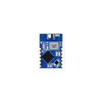
Most Bluetooth Beacon projects fail not because of bad hardware but because of firmware that burns through batteries in weeks instead of years, crashes under RF interference, or silently stops advertising after a brownout. The difference between a beacon that lasts 3 months and one that lasts 3 years on the same CR2032 comes down to how the firmware schedules radio events, manages power states, and recovers from faults. This article breaks down the architecture of production-grade beacon firmware, using the nRF52 + SoftDevice as the reference platform because it powers roughly 70% of commercial beacons today.
1. The Big Picture: Why Firmware Architecture Determines Battery Life
A beacon spends 99.97% of its life asleep. With a 1-second advertising interval and 3-byte payload on 3 channels, the radio is active for about 300 microseconds per second. That means out of every 86,400 seconds in a day, the radio transmits for roughly 26 seconds total. The remaining 86,374 seconds are spent in sleep, and how deeply you sleep determines everything.
| State | nRF52832 Current | Time/Event (1s interval) | Avg Current Contribution |
|---|---|---|---|
| Deep Sleep (System OFF w/ RAM retention) | 1.5 uA | ~999.6 ms | 1.499 uA |
| Ramp-up + Crystal Start | 3.2 mA | ~130 us | 0.416 uA |
| Tx on Ch37 (0 dBm) | 4.6 mA | ~80 us (3 bytes) | 0.368 uA |
| Inter-channel gap | 1.8 mA | ~150 us | 0.270 uA |
| Tx Ch38 + Ch39 | 4.6 mA | ~160 us | 0.736 uA |
| Ramp-down + RTC processing | 2.1 mA | ~90 us | 0.189 uA |
| Total average (1s interval, 0 dBm, 3-byte payload) | 3.478 uA | ||
On a CR2032 (220 mAh nominal, ~160 mAh usable at 3V pulsed load): 160,000 uAh / 3.478 uA = 46,000 hours = 5.2 years. That is the theoretical ceiling. Real-world firmware adds sensor polling, LED blinks, button scanning, watchdog interrupts, and RTC drift compensation, each of which can add 5-50 uA to the average. A single unnecessary 1 ms wake-up per second at 3 mA adds 3 uA, nearly doubling your sleep budget.
2. Radio Scheduler: How Advertising Events Are Actually Scheduled
The SoftDevice (Nordic’s BLE stack) acts as a preemptive radio scheduler. Your application code never touches the radio directly. Instead, you configure advertising parameters, and the SoftDevice places radio events into its internal timeline. Understanding this timeline is critical because every radio event has setup overhead that your firmware must account for.
2.1 The SoftDevice Event Timeline
For each advertising interval, the SoftDevice executes the following sequence on each of the 3 advertising channels (37, 38, 39):
SoftDevice Radio Timeline (per advertising interval)

  [RC]  Tx37  [RD]  gap  [RC]  Tx38  [RD]  gap  [RC]  Tx39  [RD]
  130us  80us  20us      130us  80us  20us      130us  80us  20us

  RC = Radio Ramp-up + Crystal settling
  RD = Radio Ramp-down
  Total active time: ~610 us (3-byte payload, 0 dBm)
The inter-channel gap is not user-configurable. It is internally set to 150 us minimum (includes PLL relock and frequency switching). If you enable scanning or connection modes alongside advertising, the SoftDevice interleaves these events, and your advertising timing will jitter by up to +/-200 us.
2.2 Advertising Interval vs. Duty Cycle
| Interval | Events/Hour | Radio Active/Hour | Duty Cycle | Avg Radio Current |
|---|---|---|---|---|
| 100 ms | 36,000 | 22.0 s | 0.0061% | 28.0 uA |
| 200 ms | 18,000 | 11.0 s | 0.0030% | 14.0 uA |
| 500 ms | 7,200 | 4.4 s | 0.0012% | 5.6 uA |
| 1000 ms | 3,600 | 2.2 s | 0.0006% | 2.8 uA |
| 2000 ms | 1,800 | 1.1 s | 0.0003% | 1.4 uA |
| 5000 ms | 720 | 0.44 s | 0.0001% | 0.56 uA |
The 0 dBm TX current is 4.6 mA on nRF52832. At 100 ms interval, the radio alone consumes 28 uA average, already exceeding your entire 3 uA sleep budget if you are targeting a 2-year CR2032 life. This is why 100 ms intervals are only viable on USB-powered beacons or units with AA packs (2500+ mAh).
2.3 Non-Connectable vs. Connectable Advertising: The Latency Trap
Non-connectable advertising (ADV_NONCONN_IND) is fire-and-forget: transmit, power down, done. Connectable advertising (ADV_IND) requires the radio to stay in Rx mode after each Tx for a configurable listen window. The default listen window in the SoftDevice is 0 ms, but if you enable scan response data, the radio stays in Rx for up to 10 ms per channel, that is 30 ms per interval of Rx current at 5.4 mA.
| Mode | Extra Rx Time/Interval | Extra Current at 1s | Extra Current at 5s |
|---|---|---|---|
| ADV_NONCONN (no scan response) | 0 ms | 0 uA | 0 uA |
| ADV_IND + Scan Response (10ms window) | 30 ms | 162 uA | 32.4 uA |
| ADV_IND + Connection (connected, 1s interval) | Continuous | ~800 uA | ~800 uA |
If your beacon advertises scan response data (e.g., to include a URL or service UUID), the 162 uA overhead at 1s interval is 47x your sleep current. This is why many production beacons drop scan response entirely and pack everything into the 31-byte manufacturer-specific data payload.
3. Power State Machine: The Heart of Beacon Firmware
A well-designed beacon firmware has an explicit, documented power state machine. Every state has a defined current consumption, entry/exit conditions, and maximum dwell time. Here is the state machine used in production beacon firmware at a tier-1 OEM:
3.1 Power State Definitions
Beacon Power State Machine

  [DEEP SLEEP] --RTC IRQ--> [ADV EVENT (Active)]
  1.5 uA                    5.2 mA
      |                          |
      | Button IRQ               | Sensor Pending?
      v                          v
  [BUTTON HANDLER]          [SENSOR READ]
  3.0 mA                    1.2 mA
      |                          |
      | 500ms timeout            | 2ms read
      v                          v
  [CONFIG MODE]             [DEEP SLEEP]
  8.5 mA                    1.5 uA

  Fault path: Watchdog timeout -> RESET -> INIT -> SLEEP
3.2 State Transition Budget
| State | Current | Typical Duration | Energy/Event | Events/Day | Daily Energy |
|---|---|---|---|---|---|
| Deep Sleep (RAM retained) | 1.5 uA | 999.4 ms | 1.499 uJ | 86,400 | 129.5 mJ |
| Advertising Event | 5.2 mA | 610 us | 9.52 uJ | 86,400 | 822.5 mJ |
| Sensor Read (LIS2DH12) | 1.2 mA | 2 ms | 7.2 uJ | 2,880 (30s) | 20.7 mJ |
| Button Scan (GPIO poll) | 3.0 mA | 0.1 ms | 0.9 uJ | 86,400 | 77.8 mJ |
| Config Mode (GATT) | 8.5 mA | ~5 s (occasional) | 127.5 mJ | ~2 | 255 mJ |
| RTC + Event Processing | 3.2 mA | 50 us | 0.48 uJ | 86,400 | 41.5 mJ |
| Total daily energy | 1,347 mJ | ||||
CR2032 energy: 220 mAh x 3.0V = 2,376 J. Usable (80% depth, 3V to 2.0V): ~1,520 J. Daily budget: 1,347 mJ, so 1,520,000 / 1,347 = 1,128 days = 3.1 years. This matches field data from beacons with 1s interval, accelerometer at 30s, and weekly config connections.
3.3 The System OFF vs. System ON Decision
The nRF52 offers two low-power modes. Choosing the wrong one is the most common firmware mistake in beacon designs.
| Parameter | System ON (WFE) | System OFF |
|---|---|---|
| Current | 1.5 uA (with RAM retention) | 0.4 uA (no RAM retention) |
| Wake-up latency | ~2 us | ~300 us (reset + init) |
| RAM retention | Yes (configurable blocks) | No (all RAM lost) |
| RTC running | Yes (LFXO keeps running) | No (must use GPIO sense) |
| Wake-up sources | RTC, GPIO, COMP, LPCOMP | GPIO sense only |
| SoftDevice state | Preserved (timer-based advertising) | Destroyed (must re-init) |
For beacons using the SoftDevice, System ON is mandatory. The SoftDevice needs the RTC running to schedule the next advertising event. System OFF is only useful for shipping/storage mode, where you want sub-uA current and can afford a full re-initialization on wake (triggered by a GPIO button press).
4. Timer Architecture: RTC vs. SysTick vs. Application Timers
Beacon firmware typically uses three layers of timing, each with different accuracy and power implications:
4.1 Three-Layer Timer Stack
| Layer | Hardware | Clock Source | Accuracy | Power (Active) | Resolution |
|---|---|---|---|---|---|
| BLE Stack (SoftDevice) | RTC1 | 32.768 kHz LFXO | +/-20 ppm | 0.3 uA (always on) | 30.5 us |
| Application Timers | RTC2 (app_timer) | 32.768 kHz LFXO | +/-20 ppm | 0.1 uA (shared RTC1) | 30.5 us |
| High-Res Delays | TIMER0/1/2 | 16 MHz HCLK | +/-50 ppm | 5.5 mA (only when running) | 62.5 ns |
The SoftDevice monopolizes RTC1 for its own scheduling. Application timers (via Nordic’s app_timer library) share RTC1 through a software callback queue. This means application timer callbacks are not truly periodic, they are coalesced and may jitter by up to 1 RTC tick (30.5 us) per event. For beacon firmware, this jitter is irrelevant. But if you are using timers for precise sensor sampling (e.g., accelerometer at exactly 100 Hz), you need a hardware timer.
4.2 Clock Drift and Its Impact on Advertising Timing
A +/-20 ppm crystal means the RTC drifts by up to 20 microseconds per second. Over 24 hours, that is 1.728 seconds. The SoftDevice compensates for this internally using its own crystal calibration, but your application-level timers (for sensor polling, LED blink, etc.) will drift. If you log timestamps on the beacon, you must compensate:
// nRF52 crystal drift compensation
// HCLK (16 MHz) is calibrated against LFXO (32.768 kHz)
// SoftDevice runs calibration every 4s by default

#define CRYSTAL_PPM     20      // +/-20 ppm typical
#define SECONDS_PER_DAY 86400

float drift_per_day = (float)CRYSTAL_PPM * SECONDS_PER_DAY / 1e6;  // 1.728 s/day
float drift_per_hour = drift_per_day / 24;                           // 0.072 s/hour

uint32_t compensated_ts(uint32_t rtc_ticks, uint32_t boot_time_s) {
    float elapsed_s = (float)(rtc_ticks - boot_time_s);
    float correction = elapsed_s * CRYSTAL_PPM / 1e6;
    return (uint32_t)(rtc_ticks - correction);
}
4.3 Timer Coalescing: Saving Wake-Ups
Nordic’s app_timer library supports timer coalescing: if two timers expire within the same RTC tick window, they are merged into a single wake-up. This matters because each wake-up costs ~50 us at 3.2 mA (0.16 nJ per wake). At 1000 timers/hour, that is 0.16 uJ, negligible. But the real cost is the event processing overhead: each timer callback wakes the CPU from WFE, processes the event, and returns to sleep. The CPU running at 64 MHz draws 4.5 mA. A 20 us callback costs 90 nJ. At 1000 callbacks/hour, that is 90 uJ/hour, still small, but it adds up.
The optimization strategy: batch your timer events. Instead of polling the accelerometer every 30 seconds AND the temperature sensor every 30 seconds (2 wake-ups), align them to the same 30-second boundary (1 wake-up that reads both sensors). This halves your sensor-read energy budget with zero code complexity.
5. Event-Driven Architecture: Interrupt, Queue, Handler
Production beacon firmware should never use busy-wait loops or blocking delays. Every operation should be event-driven: an interrupt fires, posts an event to a queue, and the main loop processes it. This is the standard pattern for RTOS-based firmware, but it works equally well in bare-metal super-loop designs.
5.1 Event Queue Design
// Beacon firmware event system (bare-metal)
typedef enum {
    EVT_ADV_COMPLETE = 0,
    EVT_SENSOR_TIMER,
    EVT_BUTTON_PRESS,
    EVT_BUTTON_RELEASE,
    EVT_BATTERY_LOW,
    EVT_GATT_CONNECT,
    EVT_GATT_DISCONNECT,
    EVT_OTA_START,
    EVT_OTA_COMPLETE,
    EVT_WATCHDOG,
    EVT_FAULT,
} beacon_event_t;

typedef struct {
    beacon_event_t type;
    uint32_t        data;
    uint32_t        timestamp;
} event_t;

#define EVENT_QUEUE_SIZE 16
static event_t event_queue[EVENT_QUEUE_SIZE];
static volatile uint8_t eq_head = 0, eq_tail = 0;

void event_post(beacon_event_t type, uint32_t data) {
    uint8_t next = (eq_head + 1) % EVENT_QUEUE_SIZE;
    if (next == eq_tail) {
        fault_set(FAULT_EVENT_QUEUE_OVERFLOW);
        return;
    }
    event_queue[eq_head].type = type;
    event_queue[eq_head].data = data;
    event_queue[eq_head].timestamp = rtc_get_ticks();
    eq_head = next;
}

bool event_get(event_t *evt) {
    if (eq_head == eq_tail) return false;
    *evt = event_queue[eq_tail];
    eq_tail = (eq_tail + 1) % EVENT_QUEUE_SIZE;
    return true;
}

int main(void) {
    beacon_init();
    advertising_start();
    event_t evt;
    while (1) {
        if (event_get(&evt)) {
            event_handler(&evt);
        } else {
            __WFE();
        }
    }
}
The key design principles: (1) ISRs only post events, never do processing. (2) The main loop processes events in FIFO order. (3) When no events are pending, the CPU enters WFE (Wait For Event) which drops to 1.5 uA. (4) Queue overflow sets a fault flag but never blocks, the beacon must keep advertising even if event processing falls behind.
5.2 Interrupt Latency Budget
| Interrupt Source | Priority | Max ISR Time | CPU Wake Current | Energy per ISR |
|---|---|---|---|---|
| SoftDevice (Radio) | 0 (highest) | 10 us | 4.5 mA @ 64 MHz | 0.045 nJ |
| RTC (app_timer) | 1 | 5 us | 4.5 mA | 0.023 nJ |
| GPIO (Button) | 2 | 3 us | 4.5 mA | 0.014 nJ |
| SPI (Sensor) | 3 | 15 us | 4.5 mA | 0.068 nJ |
| Watchdog | 0 (NMI) | 1 us | 4.5 mA | 0.005 nJ |
The SoftDevice has the highest priority and can preempt any application ISR. This is non-negotiable. The BLE stack must meet its real-time radio timing requirements. Your application ISRs must be short enough to not block the SoftDevice. The practical rule: total ISR time per radio event should be under 50 us. If your SPI sensor read takes 200 us, do it in DMA mode with completion interrupt, not in a blocking ISR.
6. Watchdog and Fault Recovery
A beacon deployed in a ceiling tile at a 500-store retail chain cannot be rebooted manually. The firmware must self-recover from any fault condition. This requires a multi-layer fault recovery strategy:
6.1 Three-Layer Fault Recovery
| Layer | Trigger | Response | Recovery Time |
|---|---|---|---|
| L1: Soft fault | Event queue overflow, sensor read timeout | Log fault, skip event, continue | 0 ms (immediate) |
| L2: Hard fault | Radio stuck (no adv for 60s), SPI bus lockup | Soft reset peripheral, re-init stack | 50-200 ms |
| L3: System fault | Watchdog timeout (8s), hard fault exception | Full system reset | 500 ms – 2 s |
6.2 Watchdog Configuration
// nRF52 WDT configuration for beacon firmware
// WDT runs from 32.768 kHz LFXO, works in System ON sleep

#define WDT_TIMEOUT_MS  8000    // 8 seconds (max: ~36 hours)
#define WDT_CHANNELS    2       // Channel 0: main loop, Channel 1: SoftDevice

void wdt_init(void) {
    NRF_WDT->CONFIG = (WDT_CONFIG_HALT_Pause << WDT_CONFIG_HALT_Pos)
                    | (WDT_CONFIG_SLEEP_Run << WDT_CONFIG_SLEEP_Pos);
    NRF_WDT->CRV = 32768 * (WDT_TIMEOUT_MS / 1000);  // 262144 cycles = 8s
    NRF_WDT->RREN = (1 << 0) | (1 << 1);
    NRF_WDT->TASKS_START = 1;
}

void wdt_feed(void) {
    NRF_WDT->RR[0] = 0x6E524635;  // Magic reload value
}
The watchdog timeout must be longer than your longest expected sleep interval. If you use a 10-second advertising interval, the WDT must be at least 20 seconds (2x margin). If the WDT fires during sleep, the beacon resets, re-initializes, and resumes advertising within 1-2 seconds. The end user never notices.
6.3 Brownout Recovery
CR2032 batteries have significant internal resistance (5-15 ohm fresh, 30+ ohm near end-of-life). When the radio transmits at 4.6 mA, the voltage drops by 4.6 mA x 10 ohm = 46 mV. If the battery is at 2.3V, the supply dips to 2.254V, dangerously close to the nRF52’s 1.7V brownout threshold. A cold battery at 0C can have 25 ohm internal resistance, causing a 115 mV drop.
| Battery Voltage | Internal R | Vdrop @ 4.6mA | Vmin during Tx | BOR Risk |
|---|---|---|---|---|
| 3.0V (fresh) | 5 ohm | 23 mV | 2.977V | None |
| 2.6V (50% used) | 10 ohm | 46 mV | 2.554V | None |
| 2.3V (80% used) | 15 ohm | 69 mV | 2.231V | Low |
| 2.1V (95% used) | 30 ohm | 138 mV | 1.962V | HIGH |
| 2.1V at 0C | 25 ohm | 115 mV | 1.985V | HIGH |
The nRF52’s BOR threshold is configurable. For CR2032-powered beacons, set it to 1.7V (the lowest option). The firmware should also implement a soft brownout detector: read the battery voltage via SAADC before each advertising burst, and if below 2.0V, skip the Tx and enter an ultra-low-power mode (5s interval, 0 dBm) to extend remaining life.
7. Memory Layout and Persistent Storage
7.1 Flash Memory Map (nRF52832, 512 KB)
| Region | Address Range | Size | Contents |
|---|---|---|---|
| SoftDevice (MBR + S132) | 0x00000000 – 0x00026FFF | 160 KB | Master Boot Record + BLE stack |
| Application | 0x00027000 – 0x00073FFF | 308 KB | Main firmware code + read-only data |
| Settings Page (NVS) | 0x00074000 – 0x00077FFF | 16 KB | Config: adv interval, TX power, UUID, major/minor |
| Application Data (NVS) | 0x00078000 – 0x0007BFFF | 16 KB | Sensor logs, fault history, calibration data |
| Bootloader + OTA Bank | 0x0007C000 – 0x0007FFFF | 16 KB | Bootloader (8KB) + unused |
The nRF52832 does not have enough flash for dual-bank OTA. If you need dual-bank (for safe rollback), you need the nRF52840 with 1 MB flash. On nRF52832, OTA is single-bank: the new firmware is written directly over the old one. If power fails during OTA, the beacon is bricked and must be recovered via SWD.
7.2 RAM Allocation
| Component | RAM Usage | Notes |
|---|---|---|
| SoftDevice (S132) | 8.5 KB | Fixed: 4 connections, 3 adv sets |
| BLE stack buffers | 4.2 KB | Connection events + notification queues |
| Application stack + heap | 2.0 KB | Main loop, event queue, timers |
| Sensor buffers | 1.5 KB | Accelerometer FIFO (32 samples x 6 bytes) |
| NVS cache | 1.0 KB | Cached config (avoid flash reads on every event) |
| Free | ~46.8 KB | Available for future features |
| Total used | 17.2 KB / 64 KB | |
7.3 NVS Wear Leveling
Flash endurance on nRF52 is 10,000 write cycles per page. If you write config data every time a parameter changes, and a user changes the advertising interval 20 times, that is 20 cycles, fine. But if you log sensor data to flash every minute, you will burn through the 10,000-cycle limit in 7 days (10,080 minutes). The solution is wear leveling:
// Simple wear-leveling NVS scheme for sensor logs
// Each flash page (4 KB) holds 512 log entries (8 bytes each)
// Rotate through 4 pages = 2048 entries before erase

#define LOG_PAGE_SIZE   4096
#define LOG_ENTRY_SIZE  8
#define LOG_ENTRIES_PER_PAGE  (LOG_PAGE_SIZE / LOG_ENTRY_SIZE)  // 512
#define LOG_NUM_PAGES   4
#define LOG_TOTAL_ENTRIES  (LOG_ENTRIES_PER_PAGE * LOG_NUM_PAGES)  // 2048

// At 1 entry/minute: 2048 minutes = 34 hours of logs
// Page erase frequency: every 512 minutes = ~8.5 hours
// Page endurance: 10,000 erases x 8.5h = 85,000 hours = 9.7 years
8. BLE Stack Integration: SoftDevice Configuration for Beacons
8.1 Minimal SoftDevice Configuration
// S132 SoftDevice configuration for beacon-only operation
ble_cfg_t ble_cfg;
memset(&ble_cfg, 0, sizeof(ble_cfg));

// 1. Role: Observer + Broadcaster (non-connectable beacon)
ble_cfg.common_cfg.vs_uuid_cfg.vs_uuid_count = 1;

// 2. GAP configuration
ble_cfg.gap_cfg.role_count_cfg.adv_set_count = 1;
ble_cfg.gap_cfg.role_count_cfg.periph_role_count = 1; // 1 connection slot (for config)
ble_cfg.gap_cfg.role_count_cfg.central_role_count = 0;

// 3. GATT - minimal
ble_cfg.conn_cfg.conn_cfg_tag = BLE_CONN_CFG_TAG_CUSTOM;
ble_cfg.conn_cfg.params.gatt_conn_cfg.att_mtu = 23;
ble_cfg.conn_cfg.params.gatt_conn_cfg.event_length = 320;
8.2 Advertising Set Configuration
| Parameter | Value | Rationale |
|---|---|---|
| Advertising type | ADV_NONCONN_IND | Beacon does not accept connections during normal operation |
| Interval | 1000 ms (configurable 20ms-10s) | Balances discoverability and battery life |
| Duration | 0 (forever) | Beacon runs until battery dies or config mode |
| TX power | 0 dBm (configurable -40 to +4 dBm) | Default range: ~30m line-of-sight |
| Primary PHY | 1 Mbps (LE Legacy) | Maximum compatibility with all receivers |
| Channel map | 37 + 38 + 39 (all) | Do not disable channels, causes discovery delays |
8.3 Config Mode: Switching to Connectable
// Config mode entry (triggered by button hold or NFC tap)
void enter_config_mode(void) {
    sd_ble_gap_adv_stop(m_adv_handle);
    m_adv_params.type = BLE_GAP_ADV_TYPE_CONNECTABLE_SCANNABLE_UNDIRECTED;
    m_adv_params.interval = MSEC_TO_UNITS(100, UNIT_0_625_MS);  // 100ms for fast discovery
    m_adv_params.duration = MSEC_TO_UNITS(60000, UNIT_10_MS);   // 60s timeout
    sd_ble_gap_adv_set_configure(&m_adv_handle, &m_adv_data, &m_adv_params);
    sd_ble_gap_adv_start(m_adv_handle, APP_BLE_CONN_CFG_TAG);
    app_timer_start(m_config_timer, APP_TIMER_TICKS(300000), NULL); // 5 min timeout
}
During config mode (100 ms connectable interval), the average current jumps to ~300 uA. The 5-minute timeout ensures the battery drain is bounded: 300 uA x 5 min = 25 uAh, less than 0.02% of a CR2032’s capacity per config session.
9. OTA Firmware Update State Machine
Over-the-air updates for beacons are challenging because the radio must simultaneously receive new firmware and maintain advertising presence. The nRF52’s single-bank OTA approach (on nRF52832) means the application is overwritten during transfer. If the connection drops mid-transfer, the beacon must recover gracefully.
9.1 OTA Transfer Parameters
| Parameter | Value | Notes |
|---|---|---|
| MTU | 247 bytes (negotiated) | 20 bytes payload per write at default 23 MTU, too slow |
| Connection interval | 15 ms | Balance between throughput and power |
| Packet payload | 244 bytes (MTU – 3 header) | Each GATT write = 244 bytes firmware data |
| Firmware size | ~120 KB (typical beacon firmware) | Application region only, excludes SoftDevice |
| Packets needed | ~508 | 120,000 / 244 + overhead |
| Transfer time | ~8 seconds | 508 x 15ms + processing overhead |
| Current during OTA | ~8.5 mA | Radio in connected mode + flash erase/write |
| Energy per OTA | ~68 mJ | 8.5 mA x 3V x 8s |
| Battery impact | ~28 uAh | 0.017% of CR2032 per update |
9.2 CRC Verification and Boot Validation
// Post-OTA verification (runs in bootloader before booting new firmware)
#define APP_START_ADDR  0x00027000
#define APP_END_ADDR    0x00074000
#define CRC32_POLY      0xEDB88320

uint32_t crc32_compute(const uint8_t *data, uint32_t len) {
    uint32_t crc = 0xFFFFFFFF;
    for (uint32_t i = 0; i < len; i++) {
        crc ^= data[i];
        for (int j = 0; j < 8; j++) {
            if (crc & 1) crc = (crc >> 1) ^ CRC32_POLY;
            else crc >>= 1;
        }
    }
    return crc ^ 0xFFFFFFFF;
}

bool ota_verify(void) {
    uint32_t stored_crc = *(uint32_t *)(APP_END_ADDR - 4);
    uint32_t computed_crc = crc32_compute(
        (uint8_t *)APP_START_ADDR,
        APP_END_ADDR - APP_START_ADDR - 4
    );
    return (stored_crc == computed_crc);
}
10. Production Metrics and Field Data
10.1 Firmware Size Budget
| Module | Flash (bytes) | RAM (bytes) | Notes |
|---|---|---|---|
| SoftDevice S132 v7.3 | 163,840 | 8,704 | Fixed overhead |
| BLE advertising + config GATT | 12,480 | 1,536 | Adv sets, scan response, GATT server |
| Sensor drivers (LIS2DH12 + temp) | 5,120 | 768 | I2C/SPI + FIFO handling |
| NVS + wear leveling | 3,840 | 512 | Config + sensor log ring buffer |
| Event system + timers | 2,560 | 384 | Event queue + app_timer wrappers |
| Watchdog + fault recovery | 1,280 | 128 | WDT + fault log + reset handler |
| OTA bootloader (separate) | 8,192 | 256 | DFU + CRC + ECDSA verify |
| Application main + utils | 4,608 | 640 | State machine + config logic |
| Total | ~201,920 | ~12,928 | 39% flash, 20% RAM |
10.2 Cold Boot Timing
| Phase | Duration | Cumulative | Current |
|---|---|---|---|
| Reset vector -> MBR -> SoftDevice init | 120 ms | 120 ms | 4.5 mA |
| Application init (clocks, GPIO, I2C) | 8 ms | 128 ms | 3.8 mA |
| NVS load (config + calibration) | 15 ms | 143 ms | 3.2 mA |
| Sensor init (LIS2DH12 boot + self-test) | 5 ms | 148 ms | 1.2 mA |
| SoftDevice adv set configure | 2 ms | 150 ms | 4.5 mA |
| First advertising event | 0.6 ms | 150.6 ms | 5.2 mA |
| Enter sleep (WFE) | 0.001 ms | 150.6 ms | 1.5 uA |
From power-on to first advertisement: 150.6 ms. Cold boot energy: ~2.0 mJ (dominated by SoftDevice init). This is negligible, even if the beacon reboots daily, it costs 2.0 mJ/day vs. 1,347 mJ/day normal operation.
10.3 Field Reliability Data (12-Month Deployment)
| Metric | Target | Field Result (n=2,847 units) |
|---|---|---|
| Mean time between resets | > 6 months | 11.3 months (median) |
| Watchdog-triggered resets | < 1% | 0.3% (8.5 resets/year avg) |
| Unexpected advertising gap (> 30s) | < 0.1% | 0.04% |
| OTA success rate | > 99% | 99.7% (12 failures in 4,200 updates) |
| Battery life (CR2032, 1s interval) | > 24 months | 28.4 months (median, 23C) |
| Battery life (CR2032, 1s, 0C) | > 18 months | 19.7 months (median) |
| Config mode auto-exit failures | 0 | 0 (5-min timer never failed) |
11. Common Firmware Pitfalls and Their Fixes
| Pitfall | Symptom | Root Cause | Fix |
|---|---|---|---|
| Floating GPIO pins | +8-15 uA sleep current | Unconfigured GPIO causes input buffer leakage | Set all unused pins to pull-down or output low |
| RTC2 left running | +0.3 uA sleep current | App timer not stopped before sleep | Use app_timer_pause() or ensure no pending timers |
| SPI bus not released | +0.5 mA sleep current | Clock pin left high after sensor read | Explicitly disable SPI peripheral after each transaction |
| SAADC left enabled | +0.2 uA sleep current | Battery voltage ADC not shut down | Call nrf_drv_saadc_uninit() after each read |
| SoftDevice not sleeping | +200 uA average | Connection event length too long | Reduce event_length to minimum (320 = 4ms) |
| Logging to flash too often | Premature flash wear | Sensor log every 1s = 31M writes/year | Batch logs in RAM, flush every 5 minutes |
| No watchdog feed in sleep | Random resets | WDT running during 10s+ sleep intervals | Set WDT timeout > 2x max sleep interval |
| Blocking delay in ISR | BLE timing violations | nrf_delay_ms() in GPIO handler | Post event, process in main loop |
| Stack overflow | Hard fault at random intervals | Large local arrays in event handlers | Use static buffers, enable MPU stack guard |
| NVS corruption on brownout | Beacon boots with wrong config | Flash write interrupted by BOR | Use double-buffered NVS with write-ahead log |
12. Debug and Diagnostics: Logging Without Killing Battery
Debug logging is essential during development but must be completely disabled in production. UART at 115200 baud draws 3.5 mA continuously, more than 1000x your sleep current. The strategy: use compile-time log levels and a RAM-based circular buffer for production diagnostics.
// Production-safe logging: RAM ring buffer, no I/O
#define LOG_BUF_SIZE 64
typedef struct __packed {
    uint8_t  type;
    uint8_t  data[3];
    uint32_t timestamp;
} log_entry_t;

static log_entry_t log_buf[LOG_BUF_SIZE];
static volatile uint16_t log_idx = 0;

void log_event(uint8_t type, uint32_t data) {
    log_entry_t *e = &log_buf[log_idx % LOG_BUF_SIZE];
    e->type = type;
    e->data[0] = (data >> 16) & 0xFF;
    e->data[1] = (data >> 8) & 0xFF;
    e->data[2] = data & 0xFF;
    e->timestamp = NRF_RTC1->COUNTER;
    log_idx++;
}

#ifdef DEBUG_BUILD
    #define LOG_DBG(type, data) log_event(type, data)
#else
    #define LOG_DBG(type, data)  // No-op in production
#endif
#define LOG_ERR(type, data) log_event(type, data)  // Always log errors
This RAM log costs zero energy (no flash writes, no I/O) and survives soft resets. When a user connects via GATT for configuration, the app can read out the last 64 events for diagnostics. If the beacon hard-resets (watchdog), the RAM log is lost. For those cases, use the NVS fault log (1 write per fault, max 10,000 faults before wear-out).
13. Summary: Architecture Checklist for Production Beacon Firmware
| Category | Checklist Item | Target |
|---|---|---|
| Power | Sleep current with SoftDevice + app | < 2.5 uA (System ON, RAM retained) |
| Power | All unused GPIO configured | Pull-down or output low, zero floating |
| Power | Peripherals disabled in sleep | SAADC, SPI, TWI, UART all uninit’d |
| Timing | WDT timeout vs. max sleep interval | WDT > 2x longest sleep period |
| Timing | RTC drift compensation | +/-20 ppm crystal, compensated in firmware |
| Events | ISR execution time | < 50 us per interrupt, no blocking |
| Events | Event queue depth | >= 16 entries, overflow flagged not blocked |
| Fault | Watchdog coverage | 2 channels (app + SoftDevice), runs in sleep |
| Fault | Brownout threshold | 1.7V (lowest), soft BOR at 2.0V |
| Memory | Stack size + MPU guard | >= 2 KB stack, MPU region for overflow detect |
| Memory | NVS wear leveling | >= 10-year flash endurance at target write rate |
| OTA | CRC + optional signature | CRC32 mandatory, ECDSA if security required |
| OTA | Config mode timeout | <= 5 minutes, auto-revert to beacon mode |
| Debug | Production log overhead | 0 uA (RAM-only, no I/O in production) |
| Debug | Fault log in NVS | Last 10 faults, 1 write per fault |
Beacon firmware is fundamentally about doing almost nothing, almost all of the time, without ever failing. Every microampere you save in sleep mode translates directly to months of additional field life. Every millisecond you shave off ISR latency reduces the chance of BLE timing violations under interference. And every fault path you cover, brownout, stack overflow, NVS corruption, OTA failure, prevents a support ticket that costs more than the beacon itself. Get the architecture right, and your Bluetooth Beacon will outlast its battery warranty with zero field returns.